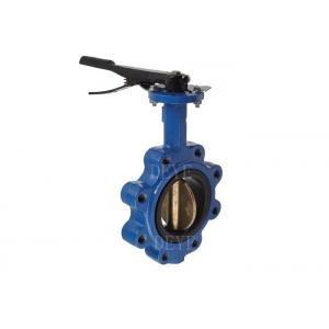
Ductile Iron GG25 GGG40 GGG50 Lug Butterfly Valves For PN10 PN16 PN25
Series No. BFV-1005
A butterfly valve, also known as a flap valve, is a simple structure regulating valve that can be used for switch control of low-pressure pipeline media. The butterfly valve refers to a valve with a disc as the closing component (valve disc or butterfly plate) that rotates around the valve axis to achieve opening and closing.
Butterfly Valves can be used to control the flow of various types of fluids such as air, water, steam, various corrosive media, mud, oil products, liquid metals, and radioactive media. Mainly used for cutting and throttling on pipelines. The butterfly valve opening and closing part is a disc shaped butterfly plate that rotates around its own axis within the valve body to achieve the purpose of opening, closing or adjusting.
Quick Detail
Design standard: API 609.
Body material: DUCTILE IRON ASTM A536
Nominal diameter: DN40 to DN1200 (1-1/2”—48”.)
Pressure: CL150 (PN20) 150PSI 225PSI, 285PSI, PN6/PN10/PN16, JI5K/JIS10K
End connection: Wafer, LUG
Face to face:EN558 Series 20
Top flange ISO5211.
Bi-direction Seal, Renewable seat Design
Mode of operation: Lever
Test and inspection: API 598. EN1226
Epoxy Powder Coated inside and outside Min. 250 microns.
Product Range
Available Body Material: Ductile Iron , Carbon steel, Stainless steel, Alloy steel.
Available Disc Material: Ductile iron, SS304, SS316, Bronze, Duplex SS2205/2507, UNS31803/UNS32750
Optional Seat: EPDM, NBR, PTFE, Teflon. Neoprene
Optional End connection: Wafer, Lug, Flanged.
Optional Body Design: Eccentric or Concentric centerline
Face to face: EN558 Series 13/14, long type or short type
Normal diameter: 4"~96" (DN100~DN2400).
Pressure range: 150lbs (PN10~PN25).
Available Operation: Gearbox, Electric, pneumatic actuator
Working temperature: -46℃~+200℃.
Performance:
- Ductile iron solid valve body, QT450-10 ductile iron valve body, tensile strength 450Mpa Min.
- Highly elastic seat rubber
The rubber content of the valve seat rubber is 50%, and the simulation of opening and closing experiments is more than 10,000 times, without leakage
- Aksu epoxy plastic powder
The valve body is sprayed with Akzo's epoxy resin powder Min. 250microns. with strong adhesion
- Anti-blowing valve shaft design
The valve shaft of of the butterfly valve adopts the anti-blowing structure, which has excellent safety performance.
Install of the butterfly valve
Figure 1
| Incorrect Disc opened beyond valve body face. Pipe flanges not spread sufficiently. | Disc positioned in the almost closed position. Pipe flange spread allows sufficient room for valve. |
 | |
Figure 2 Centering and Flanging of Valve
| Disc in closed position Gaskets installed between valve and mating flanges | Correct No flange gaskets used. Disc in the “almost closed” position. |
| |
|
Figure 3.Flange Bolt Tightening Sequence
Figure 4-Final Valve Alignment and Tightening of Flange Bolts
| Incorrect Pipe Flanges mis-aligned uneven torque applied to bolting. | Correct Piping aligned. Thread engagement even on both sides of valve. |
|
| |
Application:
widely used in gas, oil, water, chemical engineering and other related industries, also in cooling water systems of thermal power stations